# SOIL MECHANICS
# 1.1 Relationships among Unit Weight, Void Ratio, Moisture Content, and Specific Gravity
# 1.1.1 Unit Weight, Void Ratio, Moisture Content
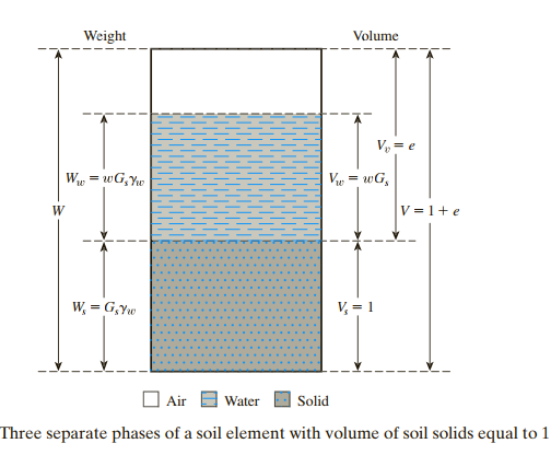
Volume of a given soil sample can be expressed as:
where:
= volume of soil solids = volume of voids = volume of water in the voids = volume of air in the voids
Assuming that the weight of the air is negligible, we can express the total weight of the sample as:
where:
= weight of soil solids = weigh of water
Void ratio (e) is defined as the ratio of the volume of voids to the volume of solids:
Porosity (n) is defined as the ratio of the volume of voids to the total volume:
The degree of saturation (S) is defined as the ratio of volume of water to the volume of voids, or:
The relationship between void ratio and porosity:
Moisture content (w) is also refered as water content and is defined as the ratio of the weight of water to the weight of solids in a given volume of soil:
Unit weight is the weight of soil per unit volume:
Soils engineers sometimes refer to the unit weight defined by Eq. (*) as the moist unit weight The unit weight can also be expressed in terms of the weight of soil solids, the moisture content, and the total volume.
The weight per unit volume of soil, excluding water, is referred to as the dry unit weight:
Weight of soil solids and water can be given as:
where:
= specific gravity of soil solids = moisture content = unit weight of water
# 1.1.2 Specified gravity
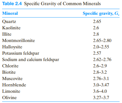
Specified gravity of soil solids (GS) can be expressed as:
Specific gravity is defined as the ratio of the unit weight of a given material to the unit
weight of water. 
Now, using the definition of unit weight and dried unit weight, we have:
and
The relationship between Gs and the volume occupied by water is:
Hence, from the definition of degree of saturation:


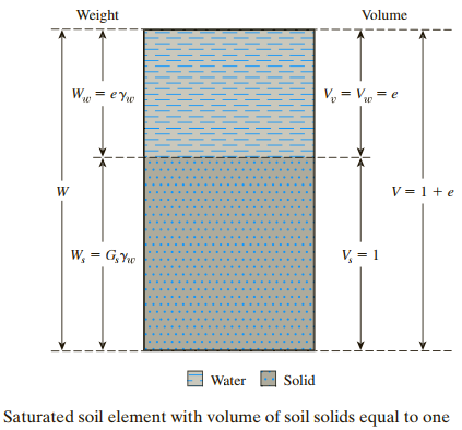
If the soil sample is saturated, that is, the void spaces are completely filled with water (figure above), the relationship for saturated unit weight {\gamma _sat} can be derived in a similar manner:
(this section is to be continued) ......
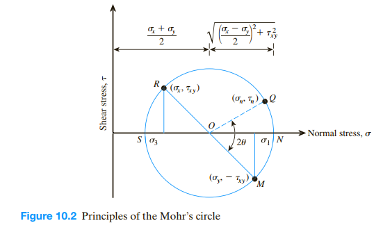
 The points R and M in Figure 10.2 represent the stress conditions on planes AD
and AB, respectively. O is the point of intersection of the normal stress axis with the line RM. The circle MNQRS drawn with O as the center and OR as the radius is the
Mohr’s circle for the stress conditions considered.
(this section is to be continued) ......
# References:
- Braja M.Das, Khaled Sobhan, Principles of Geotechnical Engineering, 2016.
- Robert D.Holtz, William D. Kovacs, An Introduction to Geotechnical Engineering, Prentice-Hall, 1981.
